A-ARM help

The 1" material from mcmaster-carr is $37 for 6'. That's $6.16 a foot. I bought it for $5.66 a foot and found it a little cheaper elsewhere but in a limited selection.

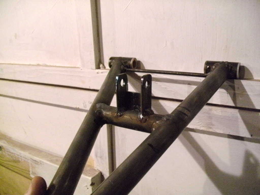
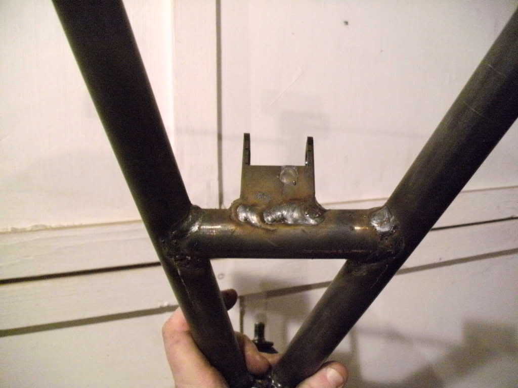
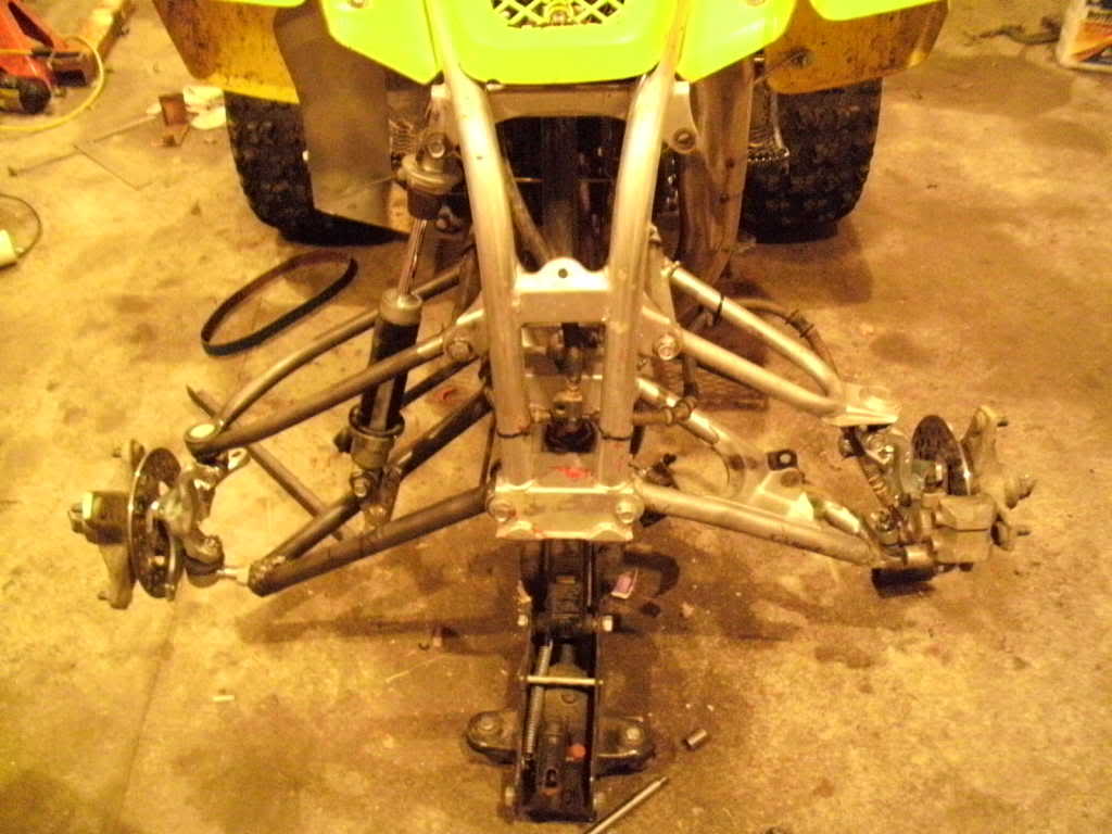
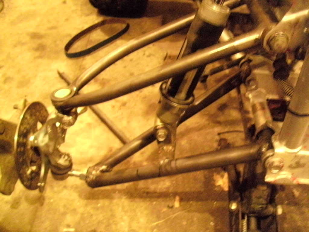
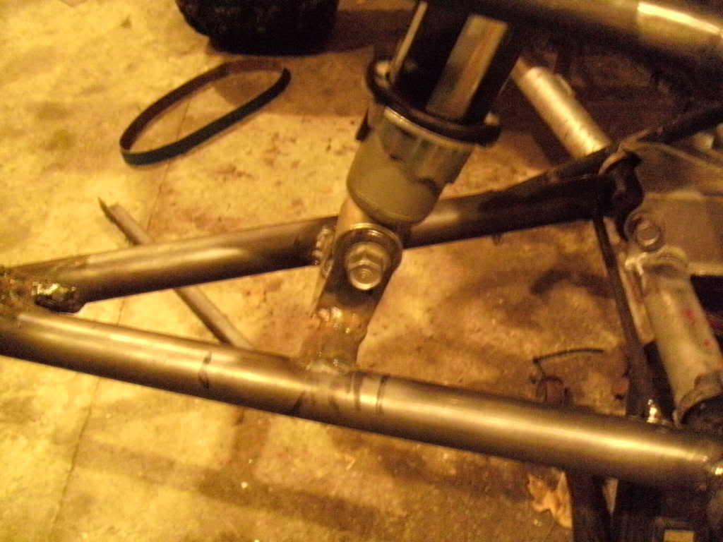
I worked on the shock mount tonight. I have the location hammered down for the making the rest of the jig but I'm not particularly happy with the right side lower control arm shock mount. I may actually purchase more 1" tubing sometime after I have rode this set of arms and rebuild the right lower control arm using the jig to make it pretty and to the dimensions I really want.

I also measured the suspension throw. 8 3/4" without bind

Pics for you people:

SANY0037-5.jpg


SANY0046-1.jpg


SANY0043-1.jpg


SANY0044-1.jpg


SANY0039-2.jpg
 
Lookin good! ... If ya still have the stock arms on the left could you measure stock bind to bind travel? one of mine is about 7 3/4", it's a warrior spindle & modded top arm but I think it's close to stock configuration. With stock shock, the travel is about 6 1/4". Be nice to have a stock baseline to see what's being gained.
Thanks
 
The stock bind to bind travel on the left side of my quad is only ~6 1/2". You can see in the second picture how much lower the new suspension is than the factory stuff and the factory stuff is sitting at bind with no shock in there and the new stuff has the shock mounted. The stock suspension really doesn't leave anything on the table so this is pure improvement.

I'm actually still not happy with that shock mount. It is leaned outwards far too much. I really only put it in there to be able to measure everything I wanted. I'm going to run it but I'm also going to change the design (but not the dimensions) for the left side so the pictures of the left side will be the new and improved design for the lower shock mount. If I make any more sets they'll be of the new design. Be patient, I'll post pics of the new design after I get it all hammered out.


Also, I have all of the measurements necessary done for the dimensions. I'm going to be doing some engineering drawings (sorry no CAD) with the measurements on them for those who would like instructions. I'll post them up in a week or two. For those who were wondering, now that I have tested the travel possible and it has passed that test, the upper ball joint is an allballs replacement lower ball joint for an 02-08 Yamaha grizzly 660. The dimensions are as follows: the pinch shaft is 14mm in diameter, the total height is 54mm, the diameter is 32mm, and the snap ring groove height is 12mm with a groove thickness of 1mm.

For anyone who does not have the capacity to make a set like this but would like to have a set made, I'm thinking about making ONE set for material cost just to test out the jig and see how pretty I can make a set for reproduction. I would do this on my own nickel but my wife would flip out if I ordered another set of metal just for testing...

Any takers? +3 arms, chro-moly, replacable ball joints...
 
man i'd love to take you up on this, just a little short on the cash lol. they'd be tested hard too lol


are they set up one, and what exactly would the cost end up being? just let me know, i'll do some scrounging ;)
 
brandoz, PM replied to. It's definitely a possibility.

I may be making these sets for retail sale if anyone else is interested. They're not going to be much cheaper than a set of ASR's (ASR really has a decent price on their product) but they'll be hand made by a blaster brother to your specific needs (shock configuration).

I'm looking for a powdercoater currently. I have a base price worked out for the material+labor but the coating may throw a monkey wrench into the works. I'm not sure how much it's going to cost to coat a set of a-arms
 
hey man, he's not around a lot anymore but callmej77 i think was his screen name had a PC setup. but it'd probably be easier if you could find something closer that you could drop stuff off
 
take this as constructive criticism...

that lower ball joint mount does not look to safe too me, whats the size of the ball joint shaft (diameter)? not to mention a lot of its shaft is showing thus allowing for a greater moment to bend it

im willing to bet that if you take a good jump or a section of whoops, that bottom mount will be toast

also, are you using a 220 welder? it doesnt look like your getting much penetration and its semi gobbed on, that shock mount wont survive either

i applaud you with your attempt, but it needs some work (not trying to be a dick)
 
without shaft showing doesn't that take away the adjustability. and also im willling to bet that these are just mockup welds and he will go back through and strengthen them. correct me if im wrong
 
most of the time a "mock up weld" is whats called a tac weld, lol and those arent tacs, thats a complete weld

and buy complete i mean like a final weld, ha he might clean it up somme, get off splatter balls and maybe if the weld is really un even but they look decent

nice job man, anything hand made and seems to be done correctly is a A+ job in my book
 
The set I took those pictures of is the mock-up set. I even went so far as to say that I wasn't happy with the shock mount and was going to change it. The left side arm is now at a better angle and should be resilient.

The plan is to order threaded tubes with the lower ball joints and put them into the mix for total inclusion into the lower arms. Take a look at most aftermarket arms. They use a tube that's the same thickness as my arm tubes and then put a nut on the backside to tighten the ball joint into it. How is that any stronger?

Those are 16mm fine threads, which is exactly the size most aftermarket arm sets use. The lower ball joints are the Ricky Stator ball joints so they're plenty strong.

I am using a 110 VAC mig with the amperage turned on position 3 of 4 to keep the warping to a minimum. For further sets I will compensate for warping by clamping and run the welder on 4 of 4 for better penetration. This ain't my first rodeo, mister.

I do appreciate positive criticism, actually. Any other issued you see?
 
without shaft showing doesn't that take away the adjustability. and also im willling to bet that these are just mockup welds and he will go back through and strengthen them. correct me if im wrong

yes, but you shouldnt have the bottom a-arm adjustable for chamber, it should be the upper a-arm... it experiences a TON less stress because it doesnt have the shock acting on it (actually the upper experiences near zero vertical loads, its just there to keep the wheel travel in a specific arc)
 
The set I took those pictures of is the mock-up set. I even went so far as to say that I wasn't happy with the shock mount and was going to change it. The left side arm is now at a better angle and should be resilient.

The plan is to order threaded tubes with the lower ball joints and put them into the mix for total inclusion into the lower arms. Take a look at most aftermarket arms. They use a tube that's the same thickness as my arm tubes and then put a nut on the backside to tighten the ball joint into it. How is that any stronger?

Those are 16mm fine threads, which is exactly the size most aftermarket arm sets use. The lower ball joints are the Ricky Stator ball joints so they're plenty strong.

I am using a 110 VAC mig with the amperage turned on position 3 of 4 to keep the warping to a minimum. For further sets I will compensate for warping by clamping and run the welder on 4 of 4 for better penetration. This ain't my first rodeo, mister.

I do appreciate positive criticism, actually. Any other issued you see?

read my above post, i like how you did the upper mount semi permanent... you should switch them and have the bottom "permanent" and put the adjustability on the top
 
hmm so he was right, good job derek

but only 110? ive welded with 110 and 220 and IMO idk why but the over all weld looks better to me with the 220 plug

but your welds look decent and i cant remember but did you say your using chromoly or just steel?
 
if your going to start making these you should go to 220, your welds will look 10 times better

that or get a TIG unit, i love mine, it was hard to switch to it, but well worth it in the end and mainly much stronger than MIG welds
 
I would love to have a 220 Mig but if I was going to do that, I'd buy a Tig and we wouldn't be having a discussion about weld quality then.

It's chro-moly except for that mount you're talking about looking all boogered and splattered on... Also, because each set of pictures was taken out in my garage while it was dark outside and my camera was catching the glint off of each weld fold and showing it really bad. I'm going to take pictures of the left side arms (the better of the two sides I've made so far) while the sun is up.
 
if your going to start making these you should go to 220, your welds will look 10 times better

that or get a TIG unit, i love mine, it was hard to switch to it, but well worth it in the end and mainly much stronger than MIG welds

yea tig is the sh*t, BUT you got to know what your doing, got to choose your tungsten tip, which filler metal, which shielding gas to keep that weld from oxidizing but most common is aragon gas

but with the tig you get a cleaner more precise weld and you can weld anymetal just buy changing your tungsten and filler metal

i love the fact that i can weld aluminum with ease now haha

i used to always burn through it with my MIG
 
I've TIG welded before and understand how much better the welds look using a TIG welder but I don't have one... I have a Lincoln Pro-mig 135 and am using it.
 
HCS-TRX450-LTXC1hr.jpg


this is what you should do, see how the lower mount has no adjustment and the shaft is all the way in? this doesnt allow for a greater moment to bend the shaft

the top has all the chamber adjustment, much stronger design