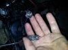
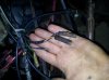
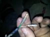
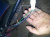
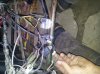
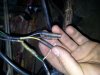
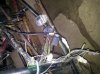
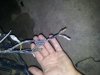
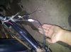
Hi i have made a go kart and have put the yamaha blaster as the rear end. I was doing some testing on how the motor ran and stuff and the first thing i noticed was that it only ran well when the petcock was on reserve. Next thing i noticed was that it only ran well when the choke was 1/4. More or less would bog it down. I was driving it and it died and now it wont start again. it may or may not have to do with these wire leads that i dont know where or what they are. I have pictures included. Please help me get my blaster back up and running and to find out what all these wires are.
Blaster on Gokart starting issue plus random wires. Need Help!
- Thread starter bmxanrchy127
- Start date
You are using an out of date browser. It may not display this or other websites correctly.
You should upgrade or use an alternative browser.
You should upgrade or use an alternative browser.
the reserve thing might mean a cogged petcock, the chocke thing is probabily because you removed the airbox completely...are you running premix(with jet increase) or did you just remove the oil pump and call it a day....somemore more pics of your whole build might give some insight....what parts did you use from the blaster, do you have the lighting killswitch and keyswitch wires still hooked up?
search the forum there is a blaster manual with a wiring diagram(with color codes iirc) that can help you trace those wires
more info is needed before you will get answers
search the forum there is a blaster manual with a wiring diagram(with color codes iirc) that can help you trace those wires
more info is needed before you will get answers
This thread has a link to a simple wiring diagram that will alow you to use only the wires you need to make it run.
http://www.blasterforum.com/engine-13/easy-wiring-diagram-you-42927/
Carb cleaning vid (for a banshee but will still mostly apply to the stock blaster carb)
http://www.blasterforum.com/do-yourself-20/carb-cleaning-how-video-39556/
http://www.blasterforum.com/engine-13/easy-wiring-diagram-you-42927/
Carb cleaning vid (for a banshee but will still mostly apply to the stock blaster carb)
http://www.blasterforum.com/do-yourself-20/carb-cleaning-how-video-39556/
This thread has a link to a simple wiring diagram that will alow you to use only the wires you need to make it run.
http://www.blasterforum.com/engine-13/easy-wiring-diagram-you-42927/
Carb cleaning vid (for a banshee but will still mostly apply to the stock blaster carb)
http://www.blasterforum.com/do-yourself-20/carb-cleaning-how-video-39556/
That wiring diagram says its for the tors system delete, what is that and how do i know if i have that?
the reserve thing might mean a cogged petcock, the chocke thing is probabily because you removed the airbox completely...are you running premix(with jet increase) or did you just remove the oil pump and call it a day....somemore more pics of your whole build might give some insight....what parts did you use from the blaster, do you have the lighting killswitch and keyswitch wires still hooked up?
search the forum there is a blaster manual with a wiring diagram(with color codes iirc) that can help you trace those wires
more info is needed before you will get answers
I got the quad from a friend and have not changed anything so everything on it is how i got it. I run premix in the quad. It did not have a key switch on it, it had the regular kill switch. I have the kill switch wired up to a regular switch , and the wires from the light(which was not on the quad when i got it) are not hooked up to anything. For the parts from the blaster, i have used the entire blaster. The frame from the blaster is welded to the back of the go kart so i use the entire rear end of the blaster.
http://www.blasterforum.com/do-yourself-20/how-remove-your-tors-655/
TORS is a system that keeps the quad from driving away if the trottle is stuck.. either when starting or when driving. There is a switch inside the thumb throttle and one inside the top of the carb. Lets say your carb is stuck WIDE OPEN when it shouldn't be... letting go of the throttle would cause the system to kill the engine due to the carb being stuck open but the throttle is closed. The problem is that a wiring fault or bad switch can cause it to do that when it shouldn't. I would wire it just enough to start/kill the motor. Once the motor is all set you can work on adding a key and head lights.
Your best bet is to cut open the wiring harness and remove any items not listed below. You will need to hack it up anyways to make everything longer.
Start with the CDI box. Wires: Black-White, Orange, Black-Red, Red-White, Black:
-Black-white is your kill switch. One side of a switch to a ground wire and one to Black-White on the CDI box.
-Orange is your coil. The wire should go right from the CDI's orange into the plug on the Coil.
-Black-red. This is goes to the black-red wire that comes out of the motor. From the motor to the CDI.
-Red-White. This goes to the Red-White wire that comes out of the motor. From the motor to the CDI.
-Black. Goes to a good ground.
GROUND THE COIL. If the coil is no longer in the stock location then you should run a ground wire to it. Crimp a black wire to an eyelet crimp then put it in with the bolt that holds the coil to your frame. Run the ground wire to a central ground location on the motor.
There may be a black wire that comes out of the motor. Ground that to the outside of the motor too.
I'm not a big fan of frame grounds for wiring. The frame should be grounded, but I always run ground wires back to a central location. Example: Pick a easy to access bolt on the motor. Remove the bolt. Take all your grounds: (One side of the kill switch, the steel section of the coil (one side), The black wire from the CDI, black wire from the motor. ), crimp round eyelets to them (or crimp them all into one). Bolt the eyelets to the motor. Also run a ground between the motor itself and the frame. You now have a very solid ground system.
Headlights: Yellow-Red from the motor. Splice yellow-red from the motor into the blue wire from the voltage regulator. It should be a small metal box with just a blue wire hanging out. Bolt the regulator to the frame so it can soak up the heat. Next, connect a third wire to the spice...Think of it like a T. Run that wire to your headlight or headlight switch. That should just about cover it.
Last edited:
http://www.blasterforum.com/do-yourself-20/how-remove-your-tors-655/
TORS is a system that keeps the quad from driving away if the trottle is stuck.. either when starting or when driving. There is a switch inside the thumb throttle and one inside the top of the carb. Lets say your carb is stuck WIDE OPEN when it shouldn't be... letting go of the throttle would cause the system to kill the engine due to the carb being stuck open but the throttle is closed. The problem is that a wiring fault or bad switch can cause it to do that when it shouldn't. I would wire it just enough to start/kill the motor. Once the motor is all set you can work on adding a key and head lights.
Your best bet is to cut open the wiring harness and remove any items not listed below. You will need to hack it up anyways to make everything longer.
Start with the CDI box. Wires: Black-White, Orange, Black-Red, Red-White, Black:
-Black-white is your kill switch. One side of a switch to a ground wire and one to Black-White on the CDI box.
-Orange is your coil. The wire should go right from the CDI's orange into the plug on the Coil.
-Black-red. This is goes to the black-red wire that comes out of the motor. From the motor to the CDI.
-Red-White. This goes to the Red-White wire that comes out of the motor. From the motor to the CDI.
-Black. Goes to a good ground.
GROUND THE COIL. If the coil is no longer in the stock location then you should run a ground wire to it. Crimp a black wire to an eyelet crimp then put it in with the bolt that holds the coil to your frame. Run the ground wire to a central ground location on the motor.
There may be a black wire that comes out of the motor. Ground that to the outside of the motor too.
I'm not a big fan of frame grounds for wiring. The frame should be grounded, but I always run ground wires back to a central location. Example: Pick a easy to access bolt on the motor. Remove the bolt. Take all your grounds: (One side of the kill switch, the steel section of the coil (one side), The black wire from the CDI, black wire from the motor. ), crimp round eyelets to them (or crimp them all into one). Bolt the eyelets to the motor. Also run a ground between the motor itself and the frame. You now have a very solid ground system.
Headlights: Yellow-Red from the motor. Splice yellow-red from the motor into the blue wire from the voltage regulator. It should be a small metal box with just a blue wire hanging out. Bolt the regulator to the frame so it can soak up the heat. Next, connect a third wire to the spice...Think of it like a T. Run that wire to your headlight or headlight switch. That should just about cover it.
Thanks for the help.
do i need to have the headlights switch wired up? Also how much power can i run for the headlights because i have a little bigger of a light i want to use then stock, i could not tell you the watts on it though.
http://www.blasterforum.com/do-yourself-20/how-remove-your-tors-655/
TORS is a system that keeps the quad from driving away if the trottle is stuck.. either when starting or when driving. There is a switch inside the thumb throttle and one inside the top of the carb. Lets say your carb is stuck WIDE OPEN when it shouldn't be... letting go of the throttle would cause the system to kill the engine due to the carb being stuck open but the throttle is closed. The problem is that a wiring fault or bad switch can cause it to do that when it shouldn't. I would wire it just enough to start/kill the motor. Once the motor is all set you can work on adding a key and head lights.
Your best bet is to cut open the wiring harness and remove any items not listed below. You will need to hack it up anyways to make everything longer.
Start with the CDI box. Wires: Black-White, Orange, Black-Red, Red-White, Black:
-Black-white is your kill switch. One side of a switch to a ground wire and one to Black-White on the CDI box.
-Orange is your coil. The wire should go right from the CDI's orange into the plug on the Coil.
-Black-red. This is goes to the black-red wire that comes out of the motor. From the motor to the CDI.
-Red-White. This goes to the Red-White wire that comes out of the motor. From the motor to the CDI.
-Black. Goes to a good ground.
GROUND THE COIL. If the coil is no longer in the stock location then you should run a ground wire to it. Crimp a black wire to an eyelet crimp then put it in with the bolt that holds the coil to your frame. Run the ground wire to a central ground location on the motor.
There may be a black wire that comes out of the motor. Ground that to the outside of the motor too.
I'm not a big fan of frame grounds for wiring. The frame should be grounded, but I always run ground wires back to a central location. Example: Pick a easy to access bolt on the motor. Remove the bolt. Take all your grounds: (One side of the kill switch, the steel section of the coil (one side), The black wire from the CDI, black wire from the motor. ), crimp round eyelets to them (or crimp them all into one). Bolt the eyelets to the motor. Also run a ground between the motor itself and the frame. You now have a very solid ground system.
Headlights: Yellow-Red from the motor. Splice yellow-red from the motor into the blue wire from the voltage regulator. It should be a small metal box with just a blue wire hanging out. Bolt the regulator to the frame so it can soak up the heat. Next, connect a third wire to the spice...Think of it like a T. Run that wire to your headlight or headlight switch. That should just about cover it.
also is there a way to do a DIY tors delete on my 2001 because the way my throttle is now theres not a way i could use the throttle switch like it should be used
A 2001 like another blaster or your gokart? If you wire it up the way I said there wouldn't be a TORS anymore.
Similar threads
- Replies
- 1
- Views
- 383
- Replies
- 0
- Views
- 102